A UML-offshoot used for Systems Engineering
SysML is a offshoot of UML 2.0 that aims to achieve Model-Based Systems Engineering (MBSE ). It supports specification analysis, design, verification and validation of a broad range of systems including hardware, software, information, processes, personnel, and facilities.
SysML is codified into ISO/IEC 19514:2017 - “Information Technology - Object Management group systems modeling language” by the Object Management Group and ISO.
Quirks of SysML
SysML model organization is up to the modeler, which frankly sucks. Folders are called packages. Package Diagrams are there to explain your organizational scheme, which means it’s not self explanatory. To make matters more confusing, there’s a difference containment and ownership. It’s possible for packages to contain elements that are owned by other elements.
V2
SysML 2.0 is coming out SOON™️ and will represent a serious, massive improvement over the current standard (my opinion). It will include a further break from UML, but in doing so a more consistent and refined language. And, most importantly, a textual language and standard API to go along with the Graphical language. Although, unlike OPM that textual language does not read like regular english.
UAF
UAF is a superset of SysML used for representing enterprise architectures.
Four Pillars of Systems & SysML
Structure
SysML uses SysML Blocks. Is a strengthened “Class” from UML. See also SysML Block Property Types andStandard SysML Block Extensions
Block Definition Diagram
BDD - How parts are related to one another
Internal Block Diagram
IBD - how parts within a single Block are connected.
Behavior
SysML has many ways to illustrate behavior.
Sequence Diagrams
SD - shows how messages are passed in order between participants.
State Diagrams
SD - also from UML. Describes states blocks can have, and how they transition between them.
Activity Diagrams
AD - for unconstrained behavior, use cases, and functional requirements.
Requirements
Requirements Diagram
REQ - What the requirements are, how they are related, what parts of the system they relate to, and how they are verified.
Parametrics
Parametric Diagram
PAR - Shows how blocks and properties are related to one another through the use of mathematical constants
Connecting the Pillars
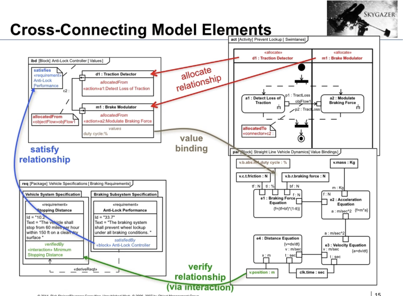
There is also the concept of “allocation” between the parts of diagrams. Parts of the activity diagram can become associated with parts inside an internal block diagram.
Requirements can be related (“satisfied”) by parts in ibd or act diagrams.
Values between parametrics and other parts of the models can be bound.
![Source: Skygazer Consulting YouTube
Source: Skygazer Consulting YouTube
Highly Related Softwares
SysML is not software-specific, but it’s well-supported by multiple software packages.
- Cameo/MagicDraw - “The Cadillac of SysML Tools”
- Visual Paradigm - available for free
- Mermaid & PlantUML - neither are truly SysML, but capable of drawing many graphs from SysML
Source
- SysML Distilled
- MIT 16 842 Fundamentals of Systems Engineering MIT Course
- YouTube
- The Four Pillars of SysML (in 30 minutes)
- SysML Open Source Project - What is SysML? Who created it?